Joan's web log
I have published Kinovea 2024.1. Currently you can get it from this forum post.
Qualitative analysis
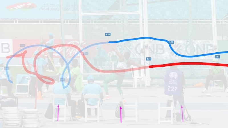
Camera motion estimation
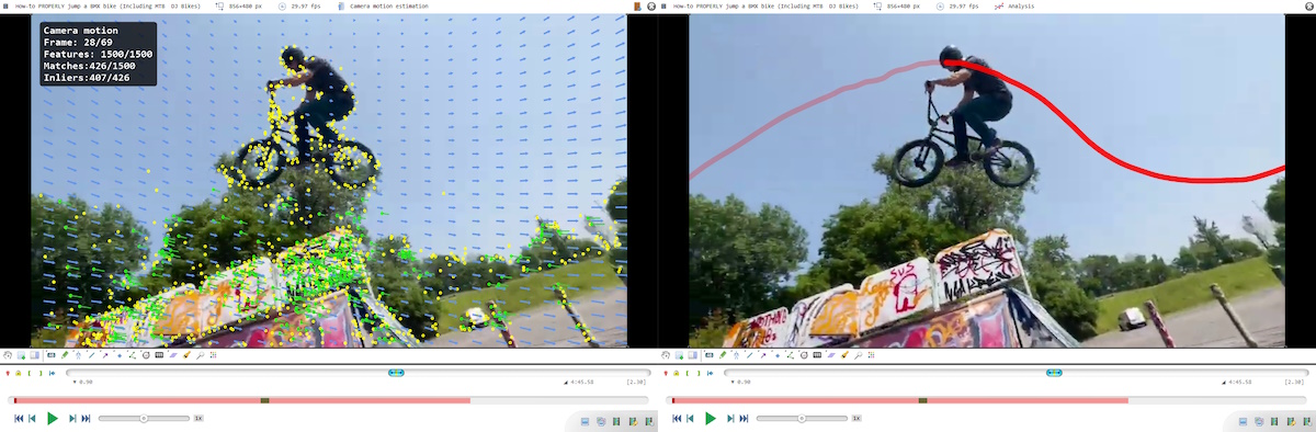
This function estimates the motion of the camera filming the video and internally produces a unified coordinate system for drawings.
This lets us add drawings and trajectories that stick to the world space of the scene.
To activate this feature go to menu Video > Camera motion estimation. This switches the player to Camera motion estimation mode. To start the estimation use the contextual menu Action > Run camera motion estimation.
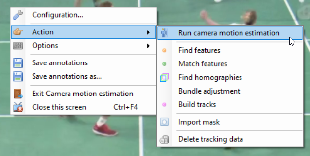
Don’t worry too much about the other menus for now. This is a large and complex feature so I added menus for each step of the algorithm and the corresponding visualization modes during development, and I left them in so that when something goes wrong we can better understand where the problem is coming from by running it step by step.
It works for rotating and zooming shots. Translation of the camera creates parallax where objects at different distances from the camera moves at different speed and this would require a full 3D reconstruction which is not implemented.
💡 Tip: At the moment the feature is usable for qualitative analysis but not for making measurements in the global coordinate system.
Kinogram
The kinogram mode now has the ability to shift each tile in time. This lets us create reports highlighting the posture at standard key moments of the motion, using fewer images at non regular intervals.
To adjust the time reference of a cell, use ALT key and scroll backward or forward with the mouse wheel while hovering above the cell.
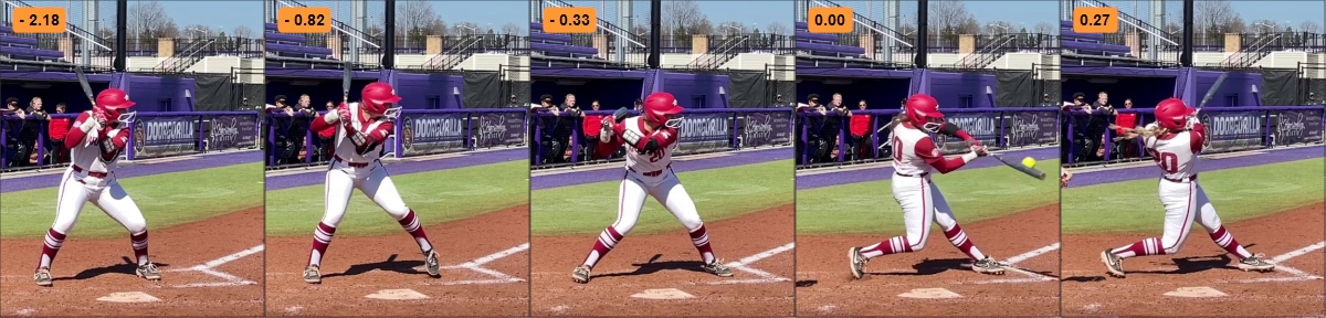
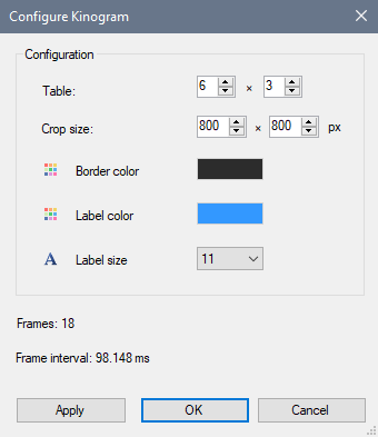
The size of the labels on Kinogram tiles (frame number or clock time) can now be configured from the Kinogram configuration dialog.
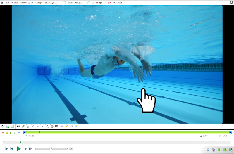
Custom pointers
For presentation purposes the hand tool can use a large image instead of the normal cursor. To enable this mode go to the main menu Options > Pointers, and select a pointer from there. This list of image-based pointers can be customized by adding new images to the “Pointers” directory under application data.
Annotations
Background layer
The background layer sits between the video image and the drawings. It can be used to make the drawings more visible against the video or, at full opacity, show only the annotations and trajectories on a plain background.
To change the background layer color and opacity right click in the background of the video and choose Background… This option is also available in the main menu Tools > Background…
Tools improvements
- The grid tool now supports different number of rows and columns and the option to display distance lines
- The text tool has an option for transparent background
- The fading and opaque duration for drawings has been increased
- The rectangle and circle tools have a new “fill” option
Measurement
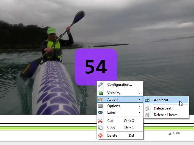
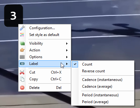
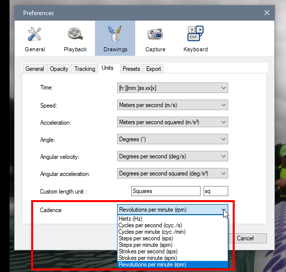
Counter tool
New in this version, the counter tool, to measure repetitions and cadence. It can be used to annotate cyclic activities: running strides, weight lifting repetitions, rotations in acrobatic sports, swimming strokes, etc.
There is more detailed information in the documentation, currently as a draft here: https://www.kinovea.org/en/forum/viewtopic.php?id=1979
Lens calibration
The lens calibration workflow has been completely revamped and it is now possible to perform lens calibration entirely inside Kinovea.
The general workflow is as follows:
- Film a calibration pattern with the camera to be calibrated
- Open the calibration video in Kinovea
- Open the dedicated lens calibration mode
- Run the automated lens calibration
- Save the resulting data to a file
- When analyzing videos filmed with the same cameras, load the saved lens calibration profile
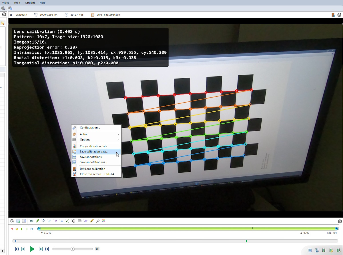
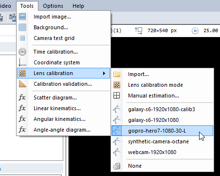
Calibration files saved to the CameraCalibration folder in the Application Data folder of Kinovea will appear in the menu Tools > Lens calibration.
I added more detailed information in this documentation draft: https://www.kinovea.org/en/forum/viewtopic.php?id=1977
Calibration validation
This is a new window dedicated to estimating the accuracy of the spatial and lens calibration. It is available from menu Tools > Calibration validation…
The idea behind this window is that you have a calibrated space and a number of “control points” for which you know the 3D position with good precision. You can then use this window to check how Kinovea reconstruct the coordinates of the points. This is useful to estimate the sort of error you will get from points that are not on the plane of motion. The dialog also contains code that reconstruct the 3D position of points from pairs of 2D coordinates. This will later be integrated in more advanced features.
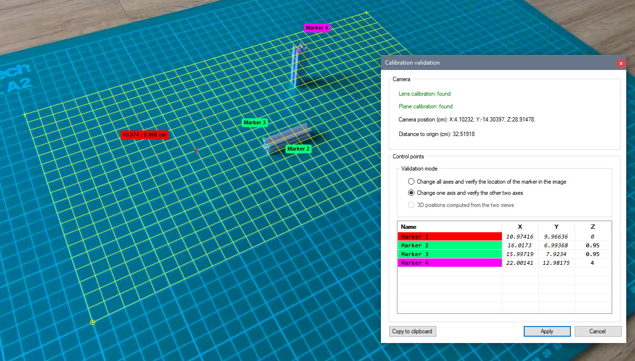
The top part of the dialog gives the camera position in 3D, in the coordinate system of the calibration grid, and its distance to the origin. You could use a laser meter to check the accuracy of this. Note: the 3D camera position is not currently used inside Kinovea except for calculating the 3D position of points inside this same dialog.
The bottom part of the dialog has 3 modes of operation:
- Change all axes and verify the location of the marker in the image.
- Change one axis and verify the other two axes.
- 3D positions computed from the two views.
All the modes assume you know the 3D positions of the control points.
With the first mode enter the true 3D coordinate of the point and it will move the marker on the image based on the calibration. You can check if it moved the marker on top of the object or if it’s off. It is expected that if you have a single camera and the object is not on the plane of motion the marker will not be aligned with the object.
In the second mode the marker is fixed in the image and you can change a coordinate (typically you would change the Z axis) to see the sort of error you get in the resulting 2D coordinates on the plane. With a single camera Kinovea assumes the points are on the calibrated plane so all marked objects are actually projections onto this plane. If the real object is not physically on the calibrated plane you will get an error in the 2D coordinate.
The third option calculates the 3D position from pairs of 2D coordinates. Markers are matched by name. This is done by tracing rays from the camera position towards the marked points on the plane and taking the intersection of the two rays. This should work even if the cameras are on the same side of the plane but they must have some distance between them for better accuracy.
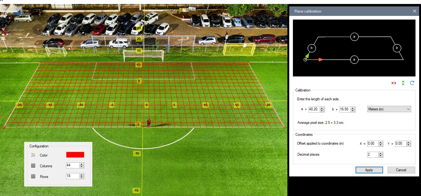
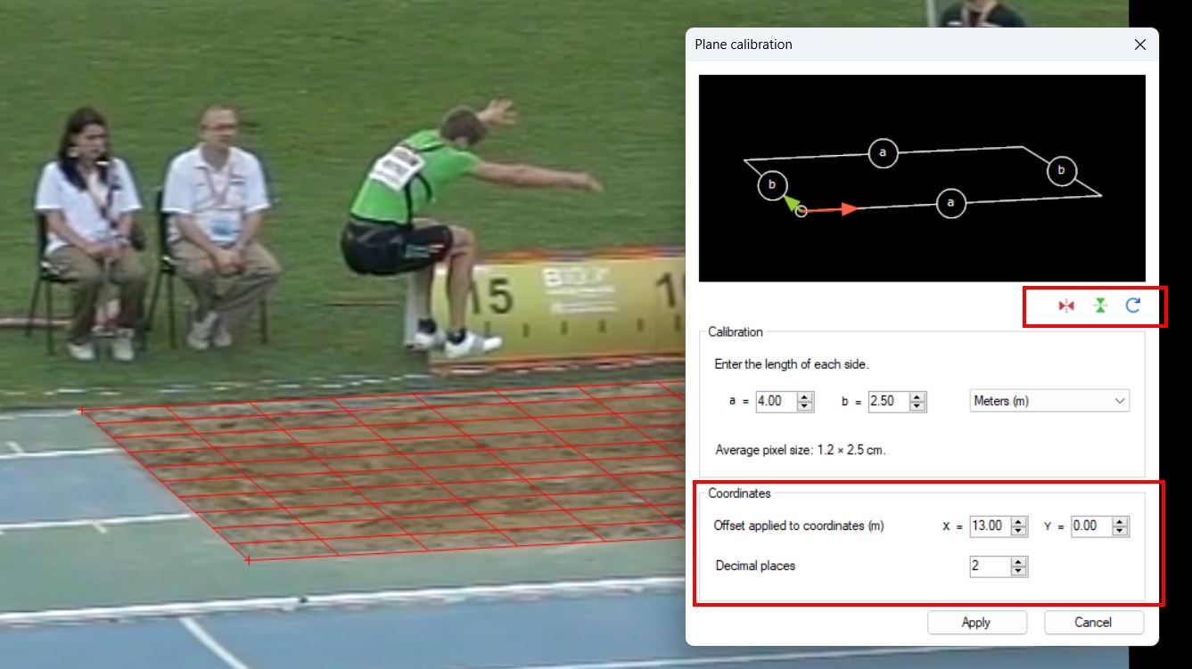
Plane calibration improvements
It is now possible to add an offset to all coordinates. This is useful if the origin of the coordinates is outside the image and not visible. In this case we calibrate the grid normally from its width and height, and then specify the position of the grid itself as an offset.
It is also now possible to rotate and flip the axes of the coordinate system with regards to the calibration grid. For example we may be calibrating a tennis court with the camera from the opposite side to where we want the origin to be. We can use the buttons below the calibration diagram. Previously we had to manually rotate the grid corners.
Lastly we can now specify the number of decimal places to show on positions and lengths.
Import/Export
The JSON export now also export key image comments.
Feedback
Please post your feedback, bug reports, usability issues, feature suggestions, etc. on the forum in the following thread.