In many scenarios it is interesting to estimate the field of view that is covered by images produced by a given camera.
The field of view depends on several factors such as the lens, the physical size of the sensor or the selected image format.
The usual techniques involve measuring an object of known width placed at a known distance, and solving simple trigonometry. This however assume that the camera uses a rectilinear lens which is not necessarily the case.
A very simple technique to estimate the field of view without knowing any intrinsic parameters of the camera has been described by William Steptoe in the following article: AR-Rift: Aligning Tracking and Video Spaces.
The idea is to place the camera in such a position that radiating lines are seen as vertical parallels on the camera image, and the center line passes through the center of the lens.
You then read the FOV by looking at the last graduation at the edge of the image.
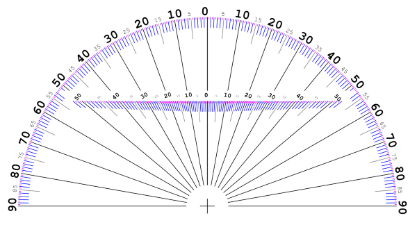
I generated a pattern to make the reading easier (fig. 1). You can download the full page PDF here:
- fovpattern.pdf (260KB).

Fig. 1. FOV estimation test pattern.
The pattern is a protractor with 0.5° granularity. The angle values start at 0 on the vertical center line and increase outward on each side. It sports a second set of graduations closer to the camera lens to help with the measurement.
If you use Kinovea to view the camera stream, you can enable the test grid tool to make sure the center vertical line is perfectly aligned with the center of the lens.
Here is an animation of the process in action.
Fig. 2. Estimating camera FOV in Kinovea using a specially crafted protractor pattern and grid overlay.
The camera should be as low as possible relatively to the pattern, but obviously not so low that you can’t see the graduations. The camera FOV is read by taking the last visible graduation on the side and multiplying it by two.
You should expect ±1° of error from the measurements.