Joan's web log
Following up on my experiments with rolling shutter calibration.
Here is a method to synchronize two off-the-shelf USB cameras with sub-frame accuracy.
Introduction
Off-the-shelf USB camera (e.g. webcams) lack the hardware to synchronize the start of exposition of multiple cameras at once.
Without this hardware support, synchronization has traditionally be limited to frame-level synchronization, where a visual or audio signal is used to temporally align the videos in post-production.
This frame-level synchronization suffers from an error ranging between 0 and half the frame period. That is, for a camera pair running at 30 fps, we may have up to 16.6 ms of misalignment. This is problematic for moving scenes in stereoscopy and other multi-view applications.
A second characteristic of these cameras is the fact that they use a rolling shutter: a given frame is constructed by staggering the exposures of the sensor rows rather than exposing the entire scene at once.
We can combine these characteristics in a simple manner to estimate the synchronization error between a pair of cameras. Manual or automatic disconnection/reconnection of one of the cameras can then be performed until the pair is under an acceptable synchronization error level.
Principle
The principle is simple and a straightforward extension to my previous post about mesuring rolling shutter.
A short flash of light will be imaged by both cameras as a narrow band of illuminated rows. In the general case the band will not be located at the same vertical coordinate in both images. The difference in coordinate is the synchronization error.
If we have calibrated the rolling shutter and know the row-delay, we can directly infer the synchronization error by counting the number of rows of difference in the image of the flash between the two cameras.
Factors to consider
Exposure duration
The exposure duration will change the width of the band. Due to the way the rolling shutter is implemented in sensor drivers, the band will increase by the bottom while the top of the band will stay in place.
The only explanation is that the exposition of each row is determined by the staggering of the readout signal (end of exposure), and when we increase the exposition these readout signals are kept attached to their temporal coordinate. It is the reset signals (start of exposure) that are moved earlier in time. Rows that are further down begin their exposition earlier than before and start to capture the flash.
I have not yet found a camera that would drive the row exposition differently.
Fig. 1. Altering the exposure duration without changing anything else makes the flash band grow by the bottom.
Frame level delay
For some framerate values, a frame-level delay may be inserted between the end of the readout of the last row and the start of the reset of the first row of the next frame. This may be referred to as the horizontal blanking period in camera manufacturer data sheets.
When this is the case, there is a dark space in the frame timing diagram. The flash may land in this space and won’t be visible in one of the camera.
Inter-frame synchronization
This procedure is only concerned with intra-frame synchronization and does not provide any clue with regards to synchronizing the streams at the frame level. In other words, even if the start of the exposures of each images is perfectly aligned in time, the synchronization could still be off by an integer number of frames. The usual frame-level synchronization cues using video or audio signals is still required.
Experimental setup
I conducted a simple experiment with two Logitech C920 cameras.
Both cameras were set to 100 µs exposure duration, and an Arduino-based LED stroboscope was used to generate flashes at a given frequency.
After the synchronization procedure was performed, the exposure and gain were set back to suitable values with regards to ambient light, without disconnecting the camera streams. The camera were then used to film a scene.
After each scene capture, the synchronization procedure was repeated to account for a small framerate drift introduced by the cameras.
A similar scene was filmed twice, the first time at less than one millisecond of synchronization error, and the second time at around 12 ms sync error.
The videos have been filmed with a parallel rig at 65 mm interaxial (Fig. 2.). The camera where set in portrait mode to maximize vertical field of view, which means that the rolling shutter was scanning horizontally. The rolling shutter itself may also cause a small amount of spatial distortion in the scene.
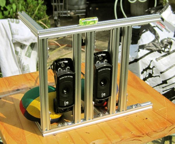
Fig. 2. Dual C920 camera rig used.
One of the camera stream has been systematically shifted up by 0.54% to correct for a small vertical disparity at the rig level. No other geometric nor radiometric synchronization was performed.
Results
The following side by side animations presents the streams in crossview order (RL): the left camera image is on the right side and the right camera image is on the left. The effect induced by the missynchronization is subtle but can be experienced by freeviewing the stereo pairs. A tutorial on how to view this type of images stereoscopically can be found here. In the missynchronized case, the balls motion induce a rivalry between the left and right eye that can be felt as some sort of blinking.
The animations run at 3 fps.
Fig. 3. Juggling sequence 1 - synchronization error: less than one millisecond.
Fig. 4. Juggling sequence 2 - synchronization error: around 10 milliseconds.
The following animations compare the synchronization artifacts on the balls in motion by overlaying the left and right images at 50% opacity. The horizontal disparity has been minimized at the plane of the face.
Fig. 5. Comparison of synchronization artifacts on objects in motion. Top: less than one millisecond of sync error, bottom: more than 10 ms sync error.
Future work
The method could be extended to any number of cameras. Manually reconnecting the camera stream is cumbersome though and an automated procedure could be developed to automatically restart the stream until the synchronization error is within a configurable value.
Another extension to this method is the synchronization of multiple cameras for super-framerate imaging. By staggering the expositions by a known amount, several cameras can be used to capture a high framerate video of the scene, provided we can correct geometric and radiometric disparities in the cameras.